This guide provides background information on why you might want to use engraving bits to mill PCBs, tips on choosing an engraving bit, and step-by-step configuration details.

Flat End Mill vs. Engraving Bit
Traditionally, we’ve recommended using flat end mills when milling PCBs on the Bantam Tools Milling Machine. Flat end mills have many advantages. Their straight profiles and consistent diameters ensure that milled traces are of a consistent width, even if the FR-1 PCB blank used isn’t perfectly flat. Flat end mills are also great at clearing large areas of material, and large flat end mills can remove material very quickly.
Flat end mills do have downsides, however. Smaller tools, particularly 1/64" and smaller, are fragile and can be easy to snap. To avoid breakage, they require slower feeds and speeds, multiple passes, and can result in long milling jobs.
Engraving bits are a fantastic alternative to flat end mills for some milling traces and pads. Because engraving bits are tapered, they’re made of more metal and are stronger and less prone to breaking than their end mill counterparts. Even very narrow engraving bits can mill successfully at comparatively high speeds and in only one pass. This makes them a great solution for quickly milling circuit boards with small features, and the recommended option for milling all traces that are too small to be milled with a 1/32" flat end mill.
Engraving bits also have tradeoffs. Because of their taper, they’re not suitable for clearing large areas of material or for milling through-holes or board outlines. Because the width of the engraving tool varies based on depth, warped or inaccurately measured boards can result in inaccurate traces. You’ll want to account for the thickness of double-sided tape or other fixturing to ensure proper depth. Also, the profile of the resulting traces are tapered, not flat, which may have implications for boards that require precise trace geometries (i.e. high-frequency circuits and antennas). Also, while engraving bits are great at isolating traces and pads, they cannot cut holes or the board outline. A flat end mill must be selected to mill holes and the board outline.
| Flat End Mill | Engraving Bit | |
| Milling Time, large areas | Fast | Slow |
| Milling time, small traces/spaces | Slow | Fast |
| Trace Profile | Square | Tapered |
| PCB Features | Traces, Holes, Outlines | Traces |
Should I use a flat end mill or an engraving bit?
While every PCB design is different, here are some rules of thumb to use when choosing tools for a job:
- If the spacing on your PCB is large enough to be milled with only a 1/32" or larger tool, use a 1/32" flat end mill to mill traces, holes, and outlines without requiring a tool change.
- If your board has features that require a tool smaller than a 1/32" flat end mill, then most often the best choice is to select a 30° PCB engraving bit. The engraving bit will be much faster than a 1/64" flat end mill, and has a smaller cutting diameter so it can cut smaller features.
- If the board requires sub-10-mil trace-and-space, an engraving bit is required.
- If the board requires 6 mil trace and space, then a 0.003” PCB engraving bit (30°) is required.
- If the board requires precise three-dimensional trace geometry, a flat end mill will provide the best results.
- If you're unsure what tools you should select, load your file into our software, select a 1/32" flat end mill, and see if there any red warnings in the software preview. If there are, keep the 1/32" flat end mill selected, and chose the 0.005” PCB engraving bit (30°). If you don't see red warnings, then keep those tools selected. If you still see warnings around traces, try adding a 0.003” PCB engraving bit (30°), and if you see warnings around a hole, add a 1/64" flat end mill.
- Remember that you'll need to use a flat end mill to cut holes and board outline. So if your board is an irregular shape, has vias, or requires both through-hole components, use both a flat end mill and an engraving bit.
What type of engraving bit should I use?
Engraving bits are classified by tip size and angle. Tip size refers to the diameter of the top of the tool, while the angle refers to the taper. A 80° bit is somewhat blunt, while a 30° bit comes to a very sharp point. Because they’re tapered, the effective milling diameter of an engraving tool varies with the milling depth.
We recommend two engraving bits: 80° and 30°.


The 30° engraving bits are sharp and come to a narrow point. They’re a good balance of precision and strength, and are what we recommend for PCB milling.


The 80° engraving bits are blunter and stronger. Although they’ll work with PCBs, we typically recommend them for traditional engraving applications such as anodized aluminum dog tags.
What types of engraving bits do we support?
We sell three engraving bits. Two are 30° engraving bits, which are most often used to mill FR-1 PCB blanks. They're called the 0.005” PCB engraving bit and the 0.003” PCB engraving bit, with 0.005" and 0.003" referring to the cutting tip size. We sell one 80° engraving bit, which is most often used to engrave metal. It's called the metal engraving bit and has a 0.005" cutting tip.
We recently renamed these engraving bits. Here's a summary of the engraving bits we sell, with both their new and old names.
| New Name | Old Name |
| 0.005” PCB Engraving Bit | 30° Engraving Bit (0.005") |
| 0.003” PCB Engraving Bit | 30° High Precision Engraving Bit (.003") |
| Metal Engraving Bit | 80° Engraving Bit |
Custom engraving bits can be created in our Custom Tool Library.
How to Configure the Software for Engraving Bit Isolation Milling
Simply select an engraving bit in a PCB configuration panel, and the software will do the rest.
Here’s a step-by-step walkthrough:
1. Measure the thickness of your PCB blank using digital calipers, and enter the thickness into the Material Size Thickness (z) field. 
2. If you’re using double-sided tape to attach your PCB blank to the milling machine, measure its thickness with calipers, and add an additional z-offset in the Material Placement Thickness (z) field. This will ensure that the engraving bit is milling to the intended depth on your material. Skipping this step is the most common reason for poor results.
3. Import a circuit board design file. 
4. Select an engraving bit for traces. 
5. (Optional) Select an end mill for holes and outlines. 
Changing Trace Depth
When milling PCBs with engraving bits, the software defaults to a 0.008" (0.20 mm) trace depth. The trace depth is the distance in the z-axis that the end mill will cut. If you wish to change the trace depth, click Advanced and change the value.
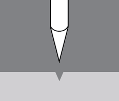
Remember that as you cut deeper, the V-shaped engraving bit will cut a wider path. If the Trace Depth is changed from the default to a larger value, the same cutting tool might become too large to cut the board.
Likewise, if you reduce the Trace Depth setting, the engraving bit will cut a narrow path. Sometimes this will cause the milling machine to make two passes around a feature, as the software is trying to make sure it cuts away enough material as indicated in the Trace Clearance setting. Trace Clearance is the amount of material that is removed around traces and pads. If you enter a very high number, like 10.0", then the milling machine will remove all copper that is not a trace or pad. Alternately, if you enter a Trace Clearance value of 0.001", then the milling machine will only make one pass around each feature.
If you change the default settings for Trace Depth and/or Trace Clearance and you want to know how many passes will happen around a given feature, look at the software preview and zoom in to see where the toolpaths are.
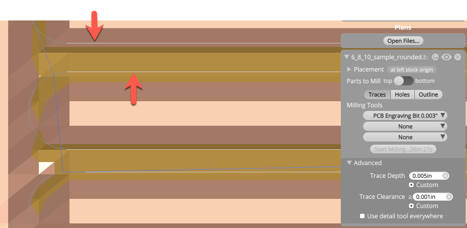
With a Trace Depth reduced from the default to 0.005" but the Trace Clearance kept at the default, there are two passes along each edge of a trace.
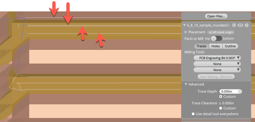
With a Trace Depth also at 0.005" but the Trace Clearance lowered to 0.001", there's only one pass along the edge of the trace.