Difficulty Level

In this intermediate project, we’ll show you how to make this low-profile wallet. The wallet has features on both the top and bottom and will require multiple operations on the Bantam Tools Desktop CNC Milling Machine.
In the first operation, you’ll face the stock and machine the slots for the wallet’s strap. In the second operation, you’ll flip the part, re-tape the workpiece, and rough out the wallet before cleaning up the walls and adding the chamfers. And then in the final step, you’ll have the option to flip the part again to add chamfers and a custom engraving on the backside.
In this project you’ll learn:
- How to adjust a stock Setup and generate G-code files in Fusion 360
- How to flip a part
- How to fixture with high-strength, double-sided Nitto tape
- Tips for programming chamfer toolpaths in Fusion 360
TOOLS
- Bantam Tools Desktop CNC Milling Machine
- Computer with Bantam Tools Desktop Milling Machine Software installed
- Computer with Autodesk's Fusion 360 software installed
- Probing pin, 1/4”
- Probing pin, 1/8”
- Datron stepped end mill, 12 mm
- Flat End Mill, 1/16”
- Datron single-flute flat end mill, 6 mm
- Harvey Tool 45º 3-flute chamfer cutter, 1/8”
- 80º metal engraving bit, 1/8”
- High-strength, double-sided Nitto tape
- ER-11 1/8” collet
- ER-11 6 mm collet
- Scraper
- Isopropyl alcohol, 91%
- Parallel (1)
MATERIALS
- Aluminum stock, 4” x 4”x 0.25”
FILES
- Low-Profile-Wallet-Project.f3d file downloaded
A Note Before You Start Milling
The Fusion 360 project files we provide are programmed specifically for the tooling and materials listed above. If you don’t have these end mills or stock, you will need to adjust the speeds and feeds parameters for the tooling and stock you're planning to use before you post-process your G-code files and set them up in the Bantam Tools Milling Machine Software. For more insight into programming toolpaths in Fusion 360, see our Fusion 360 Workflows: Programming CAM support guide.
Step 1: Install the 1/4” probing pin.
Under the Initial Setup tab, go to the Install Tool dropdown menu and click the Install Tool button. When you do, the spindle will move to the center of the machine.
- Loosen the collet nut about halfway.
- Insert the tool into the collet all of the way, and then back off slightly.
- Tighten the collet nut using the included wrenches.
- Select 1/4” Probe in the drop-down menu, and click Next.
Step 2: Prep and fixture your stock.
Next, prep and load your stock into the Bantam Tools Desktop CNC Milling Machine. Navigate to the Material Setup tab. Using digital calipers, measure the dimensions of your stock and enter them into the X, Y, and Z values in the Material Size dropdown menu. When you’re finished click Next.
To hold our material to the bed we are going to be using high-strength, double-sided Nitto tape. Double-sided tape is a great fixturing option for when you’re machining thin pieces of stock. And don’t worry, it’s strong––so strong that you may need 91% isopropyl alcohol to remove your part from the T-slot bed.
To prep your stock:
- Wipe down the T-slot bed using 91% isopropyl alcohol to ensure the bed of the machine is clean.
- Make sure the surface of your aluminum stock is clean (if not, clean it 91% isopropyl alcohol) and cover as much surface area as you can with tape. Make sure the strips don’t overlap or wrinkle because this will affect your Z thickness.
- Remove the paper backing from the tape after applying.
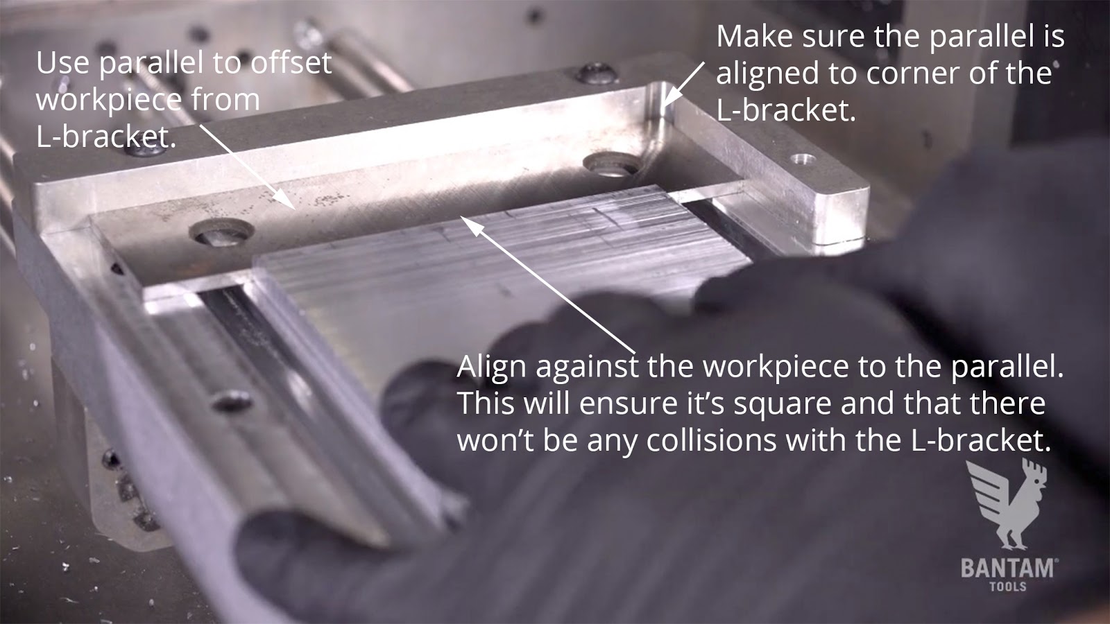
- Take one of your parallels and place it so that it’s up against the corner of the L-bracket.
- Then, press the material into place on the T-slot bed using the parallel as a backstop and center it in the bed. This will allow us to machine below the top surface of the bracket without running into it.
- Remove the parallel when you’re finished.
Step 3: Locate your stock and adjust Z height in Fusion 360.
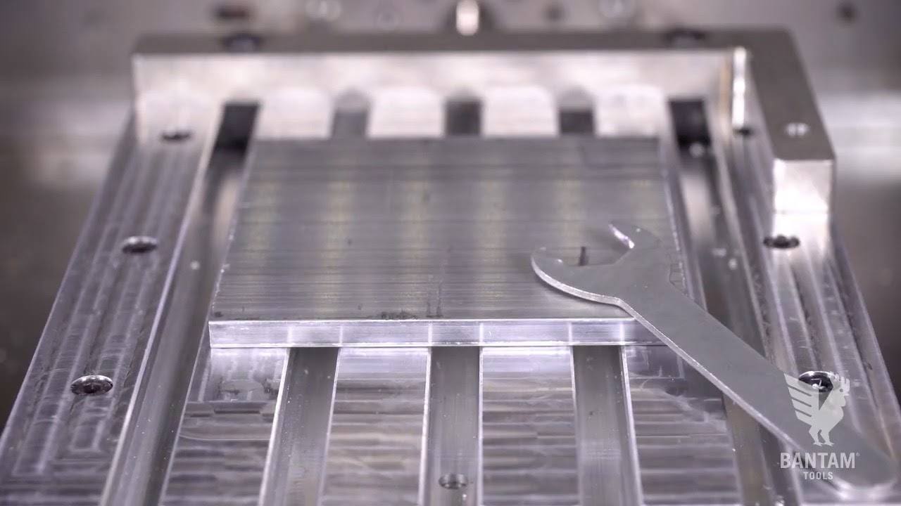
Go to the Material Placement dropdown menu, click the Material Offset Probing Routines button, and launch the Automatic Stock Probing routine. Follow the prompts and carefully lay our wrench across the piece so that it’s touching the aluminum bed. This is a trick we use to close the conductive loop between our stock and the T-slot bed when we’re using double-sided tape.
For this job, we’ll also need to enter the thickness of our tape as a Z offset to account for the thickness of the double-sided tape. The high-strength, double-sided Nitto tape we sell in our store ranges from 0.006” to 0.007” thick. For this project, go to the Material Setup tab > Material Placement dropdown menu > Material Placement and enter 0.007” for the Z offset.

Note: Because our work coordinate system (WCS) in Fusion 360 was aligned to the top, front, left stock box point, you will only need to run the Automatic Stock Location, since your plan automatically aligns with the top, left edge of the stock.
Step 4: Update your Fusion 360 Setup and generate your G-code for Setup 1.
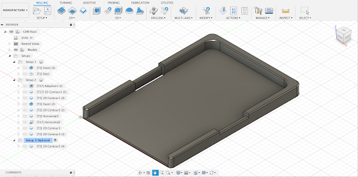
Speaking of plans, let’s generate your G-code files! If you haven’t already, launch Fusion 360. Then, go to File > Open > Open from my computer > and then select the Low-Profile-Wallet-Project.f3d file. Your screen will look like this:
Now that you’ve located the stock, you’ll need to adjust the Z height of your Fusion 360 setup so that the two values are exactly the same. This will ensure the measurements in all the files you’re going to mill will be accurate and precise. Here are the steps for adjusting the Z height of your Fusion 360 Setup.
- Right-click on Setup1 folder
- Select Edit
- Go to the Stock tab in the pop-up window
- Go to Height (Z) and enter the value of your Z height that’s showing in the Bantam Tools software
Because you’ve updated the project file’s Setup, you will need to regenerate the toolpaths we’ve programmed. To do this, right-click on the Setup1 folder and select Generate.
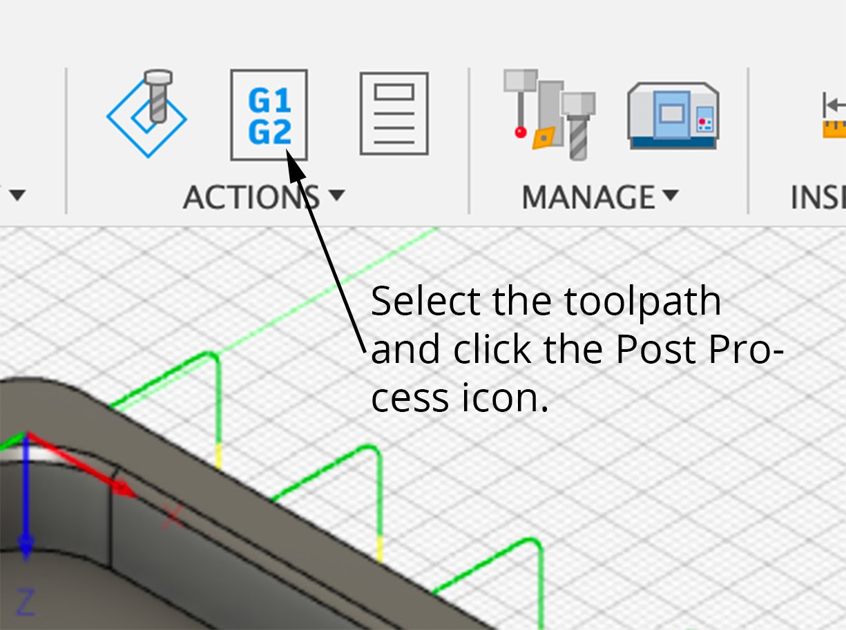
Now you can post-process each of these toolpaths as G-code files for Op1! One-by-one select each toolpath and select Post Process––or go to Actions in the toolbar and click the Post Process icon. You’ll be prompted to name your files. We suggest naming the files so that they either match or are similar to the names we’ve designated.
Step 5: Import files, install tool, and machine Setup 1.
Now that you’ve generated your G-code files for Setup 1, it’s time to import them into the Bantam Tools software. Remember, Setup 1 will consist of two operations. In the first operation, you’ll face the backside of the stock using the Datron 12 mm stepped end mill and then in the second setup, you’ll machine the slots using a 1/16” flat end mill.
Before you can install and locate your Datron 12 mm stepped end mill, you’ll need to install the 6 mm ER-11 collet into the Bantam Tools Desktop CNC Milling Machine.
To install the collet:
- Remove the collet nut from the bottom of the tool holder. Use the smaller wrench on the flat part of the tool holder to secure it in place, and then use the larger wrench to unscrew the nut.
- Remove the 1/4” collet from the collet nut.
- Insert the 6 mm collet into the collet nut—you’ll hear it snap into place.
- Screw the collet and collet nut back onto the tool holder with two or three turns, or use the wrenches, if necessary. Remember, don’t fully tighten the nut without a tool inserted.
Then, go to the Summary tab and when you’re ready, select Mill All Files. After the machine is finished facing the stock, you’ll be prompted to change your tool.
Take out the Datron end mill and remove the 6mm collet from the collet nut. Install the 1/8” ER-11 collet using the same steps outlined above. Continue to follow the on-screen prompts to finish installing and locating your 1/16” flat end mill and continue machining.
Step 6: Flip workpiece.
Alright, Setup 1 is complete! Time to flip your workpiece.
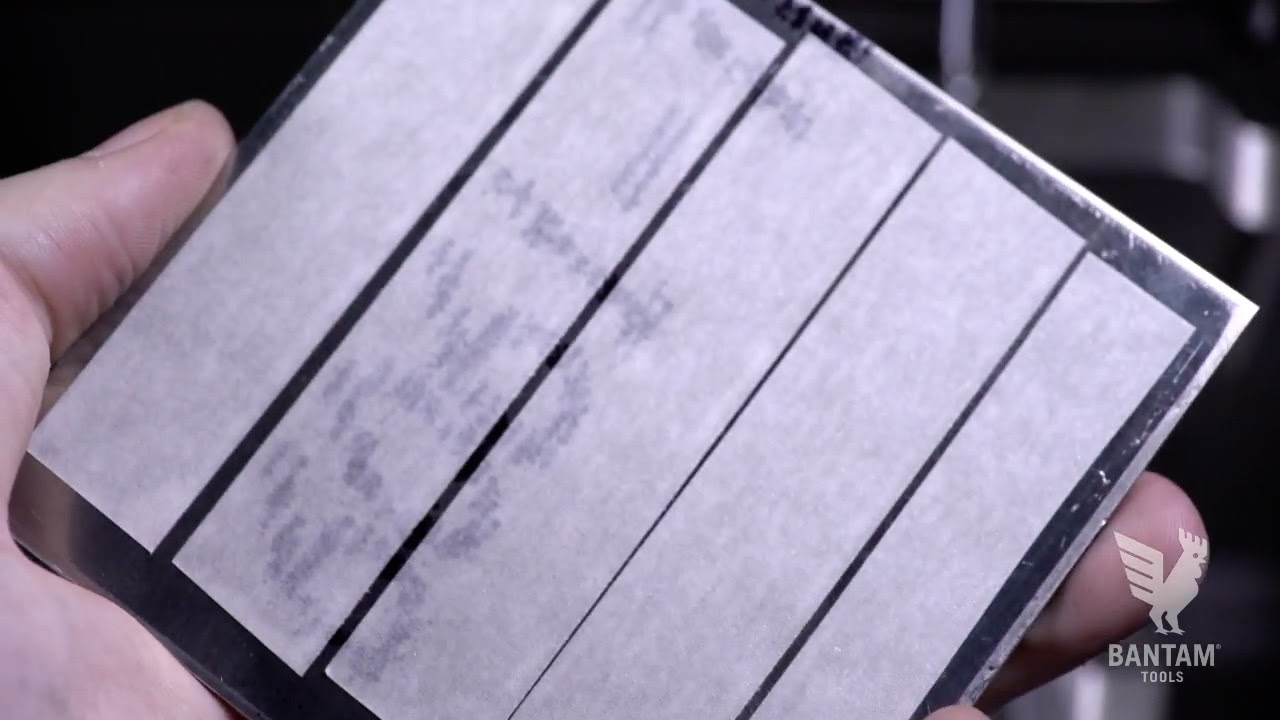
Apply 91% isopropyl alcohol around the workpiece to help dissolve the Nitto tape’s adhesive. and carefully mark the front edge of the stock so that you know which way to orientate the workpiece when you flip it.
Here is an overview of how to set up your material in the Bantam Tools software. Refer back to the previous steps if you need further reference.
- Repeat the instructions outlined in Step 2 to clean and prep your workpiece. Tape the side that was just faced.
- Then use your parallel to offset your stock (also seen in Step 2) and press the part back into place using this parallel as a backstop. The marked edge of the stock should face the front of the mill.
- Install a 1/8” probe or insert a 1/8" shank tool upside down and perform a tool touch off.
- Go to the Material Setup tab > Material Placement dropdown menu > Material Offset Probing Routines Button > Automatic Stock Probing. Follow the onscreen prompts.
- Just like you did in Step 3, lay the wrench back over the part and T-slot bed to close the conductive loop. and again run the material location routine.
Step 7: Update Fusion 360 Setup and generate G-code files for Setup 2.
Just like you did in Step 4, take the thickness reported from the probing routine and enter it into Fusion 360. Remember, go to the Stock tab in your Setup and enter the value into the Z height. When you’re finished, regenerate your toolpaths, and post-process your G-code file.
Time Out! Fusion 360 Quick Tip
When designing this wallet in Fusion 360, we knew that we wouldn’t be able to machine chamfers all the way to the walls of the two slots on the front side of the wallet. To avoid collisions we adjusted the tangential extension settings in the 2D contour to have a negative value.
To adjust this setting on your own designs, go to:
- Geometry tab in your 2D contour toolpath
- Enter a negative value into the Tangential Extension Distance.
- Check the Separate Tangential End Extension box.
- Enter the same value you did for the Tangential Extension Distance
This is what the chamfer will look like after it’s been machined.

Okay, back to machining!
Step 8: Rough out the part.
Once you’ve exported your G-code files, import the following files for Setup 2 into the Bantam Tools software:
- 3D Adaptive Roughing
- Internal 2D Contour
- External 2D Contour
- Front Facing
We’ll rough out the part and leave 0.010” on the walls that we’ll clean up the top with a horizontal pass later on. Then we’ll run contour passes to clean up the inner and outer walls. Something to remember as you start to program your own contour finishing passes is to leave an offset on the floor of your part so that the end mill is only engaging the sidewalls.
When you load the 3D adaptive roughing G-code file into the Bantam Tools software, you can zoom all the way in and verify that this operation will go to the bottom of the stock and stop just at the tape. You can also check that with that 0.007” tape offset you entered earlier that you won’t machine into the bed.
Swap in the 6 mm ER-11 collet and then install and locate the Datron 6 mm single-flute tool. After performing your tool touch-off, go to the Summary tab and when you’re ready, click Mill All.
Step 9: Machine chamfers.
You’re on the home stretch! Import the following files into the Bantam Tools Desktop Milling Machine Software to finish Setup 2:
- 2D Contour Chamfer1
- Horizontal1
- Horizontal2
- 2D Contour Chamfer2
- 2D Contour Chamfer3
Install your 1/8” ER-11 collet once more. Then install your Harvey Tool 45º chamfer cutter and locate the tool. Go to the Summary tab, select Mill All, and watch the Desktop CNC Milling Machine finish your low-profile wallet!
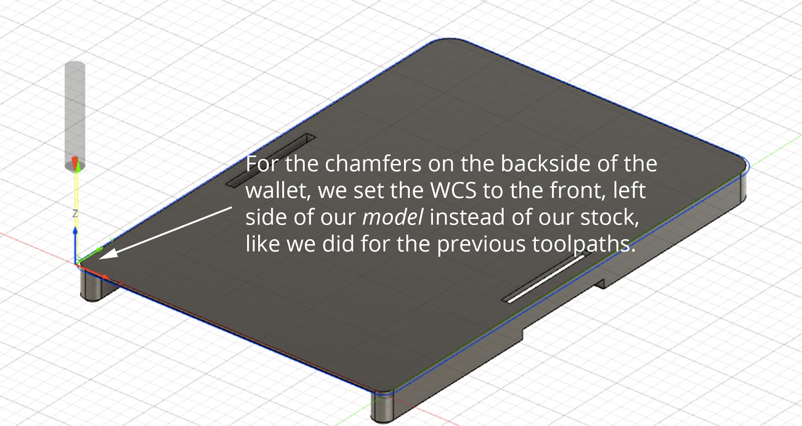
Step 10 (Optional): Add chamfers to the backside of the wallet.
If you’re on a roll with all these flips, tool changes, and probing automatic routines, you can keep going. If not, feel free to skip this step and start enjoying your new EDC wallet.
Still here? Right on!
Remove the wallet from the Desktop CNC Milling Machine and carefully apply double-sided Nitto tape to the top of the wallet’s side walls. Again, offset the part using a parallel. Then probe the front, left edge.
Head over to Fusion 360 to update your Setup, regenerate your toolpaths, and post process the optional 2D contour toolpath under Setup 3. You’ll notice that for this file, the WCS is set to the front left model box point. This setup will allow you to chamfer the backside of the part.
Just like you have for the previous operations, load your G-code file into the Bantam Tools software, head down to the Summary tab, and when you’re ready click Mill Single File.
In addition to machining this final chamfer, you can use the Bantam Tools Desktop Milling Machine Software’s built-in SVG support to add a custom engraving! To learn more about designing SVGs and using them in our Bantam Tools software, check out our Classic & Advanced Workflows support guide.
Step 11: Remove your new EDC wallet.
When you’re finished, remove your new low-profile wallet, add an elastic strap, and enjoy!
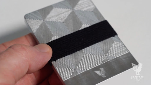
We’d love to see how your new EDC wallet turned out. Tag us on Instagram, Twitter, or Facebook to share!