The Bantam Tools Desktop CNC Milling Machine ships with a pre-installed T-slot bed, as well as an L-bracket and toe clamps for easy and rigid workholding. The L-bracket is also factory-installed and is pre-aligned to the X-axis on the back of the T-slot bed.
If you’re new to CNC machining, we suggest leaving the L-bracket installed on the back of the T-slot bed until you get more comfortable with your Desktop CNC Milling Machine. As you start machining more advanced projects, you may need to move the L-bracket around the T-slot bed. After doing this, you’ll want to realign the bracket parallel with the X-axis (also known as tramming), because even a small misalignment can lead to parts not fitting together correctly or features on a single part not lining up.
Note: If you’d like to dive deeper into why slight differences in bracket alignment can be troublesome, check out Harvey Tool’s Best Practices of Tolerance Stacking.
There are two different methods you can use to realign your L-bracket. The first is using a dial indicator and ER-11 4 mm collet. For the most accurate results, we recommend using the dial indicator, but you can also realign the L-bracket using the 1/4” probe—although it’ll require a bit more guess and check.
Method 1: Realignment with the Dial Indicator
Step 1: Install the L-bracket.
Connect the Bantam Tools Desktop CNC Milling Machine to your computer and launch the Bantam Tools software. Home the machine when prompted. Then go to the Job tab and click the Load button to bring the T-slot bed to the front of the machine.
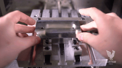
Next, install the L-bracket where you wish to align it, as close as possible to the edge of the T-slot bed. Then, tighten the screws but not all the way. You should be able to wiggle the L-bracket if you push on it with a little bit of pressure.
Note: For more guidance on installing the L-bracket onto the T-slot bed, see our Fixturing support guide.
Step 2: Install the ER-11 4 mm collet.
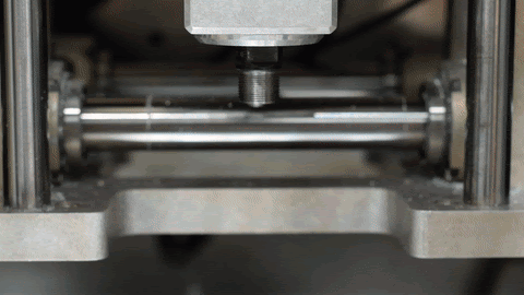
Using the Jog menu, jog the spindle to the middle of the Desktop CNC Milling Machine. Remove any end mill and collet you may have installed in the machine. Then install the ER-11 4 mm collet onto the bottom of the spindle.
Remove the collet nut from the bottom of the spindle shaft by using the smaller wrench on the flat part of the spindle shaft to secure it in place while loosening the nut with the larger wrench.
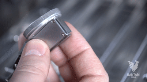
Insert the collet into the collet nut. It might wiggle a little, but putting it on the tool holder will pop it into place. You might also notice the inside of the collet has an offset. This is part of the collet’s design.
With the collet in place, thread the collet nut back onto the tool holder by hand. Tighten by two or three turns, holding the tool holder in place with the small wrench if necessary.
Note: Do not fully tighten the nut without the dial indicator inserted.
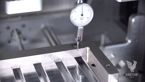
Step 3: Install the dial indicator.
Grab your dial indicator and attach the 5/32” stem that comes with it onto the provided grooved nut. It slides and locks into place on the top edge of the dial indicator by turning the stem clockwise (remember: righty tighty, lefty loosey).
With the dial facing the front of the mill, slide the dial indicator into the tool holder and tighten the collet nut completely.
Step 4: Align the L-bracket.
Jog the mill to get the dial indicator close to the screw nearest the elbow. Then use the fine step controls to move the dial indicator into place where the ball on the dial indicator makes contact with the bracket. Make careful, small adjustments until you get the gauge on the indicator to read close to zero. You can turn the dial on the gauge to get the needle to line up with zero exactly.
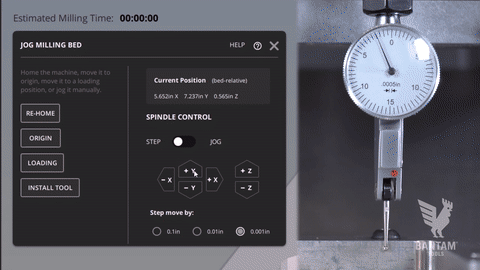
Using the jog and step controls in the Jog menu, move the dial indicator into place by the second screw.
It’ll likely give you a reading above or below zero. Slightly move that side of the bracket forward or back until the gauge reads zero. Use the other screw as your pivot point. The goal is to leave it in place, making adjustments to only one side of the bracket. Then carefully tighten the screws on the bracket completely.
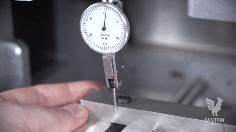
If done correctly, the gauge should now read zero when touching the bracket by both the screws. If it doesn’t, repeat the process, making small adjustments to the bracket position.
Method 2: Re-Alignment with the 1/4” Diameter Probe
Step 1: Install the L-bracket.
Connect the Bantam Tools Desktop CNC Milling Machine to your computer and launch the Bantam Tools software. Home the machine when prompted. Then go to the Job tab and click the Load button to bring the T-slot bed to the front of the machine.
Next, install the L-bracket where you wish to align it. Align it to as close as possible to the edge of the T-slot bed. Then tighten the screws but not all the way. You should be able to wiggle the L-bracket if you push on it with a little bit of pressure.
Step 2: Install the 1/4” diameter probe.
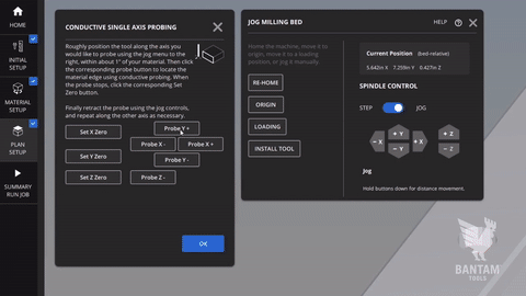
In the Jog tab, click the Install Tool button and select the 1/4” Diameter Probe. Follow the on-screen prompts to locate your tool by performing a tool touch-off.
Step 3: Load a plan.
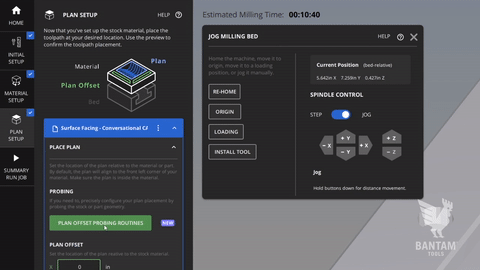
Go to the Initial Setup tab and import a plan of your choosing. We like to use a simple SVG, but you can use whatever file you want. Once you’ve loaded your plan, go to the Plan Setup tab and click the Plan Offset ProbingRoutines and select Conductive Stock Probing.
Step 4: Probe the L-bracket
Using the jog controls in the pop-up window, move the probe into position along the L-bracket near the screw closest to the elbow. Keep jogging it along the Y-axis until the probe touches the L-bracket. We recommend having Steps selected for this procedure so that you have more control over how far and fast the spindle moves. The T-slot will slowly move the probe until it makes contact with the bracket. When it stops moving, take note of its Y-position in the Jog menu.
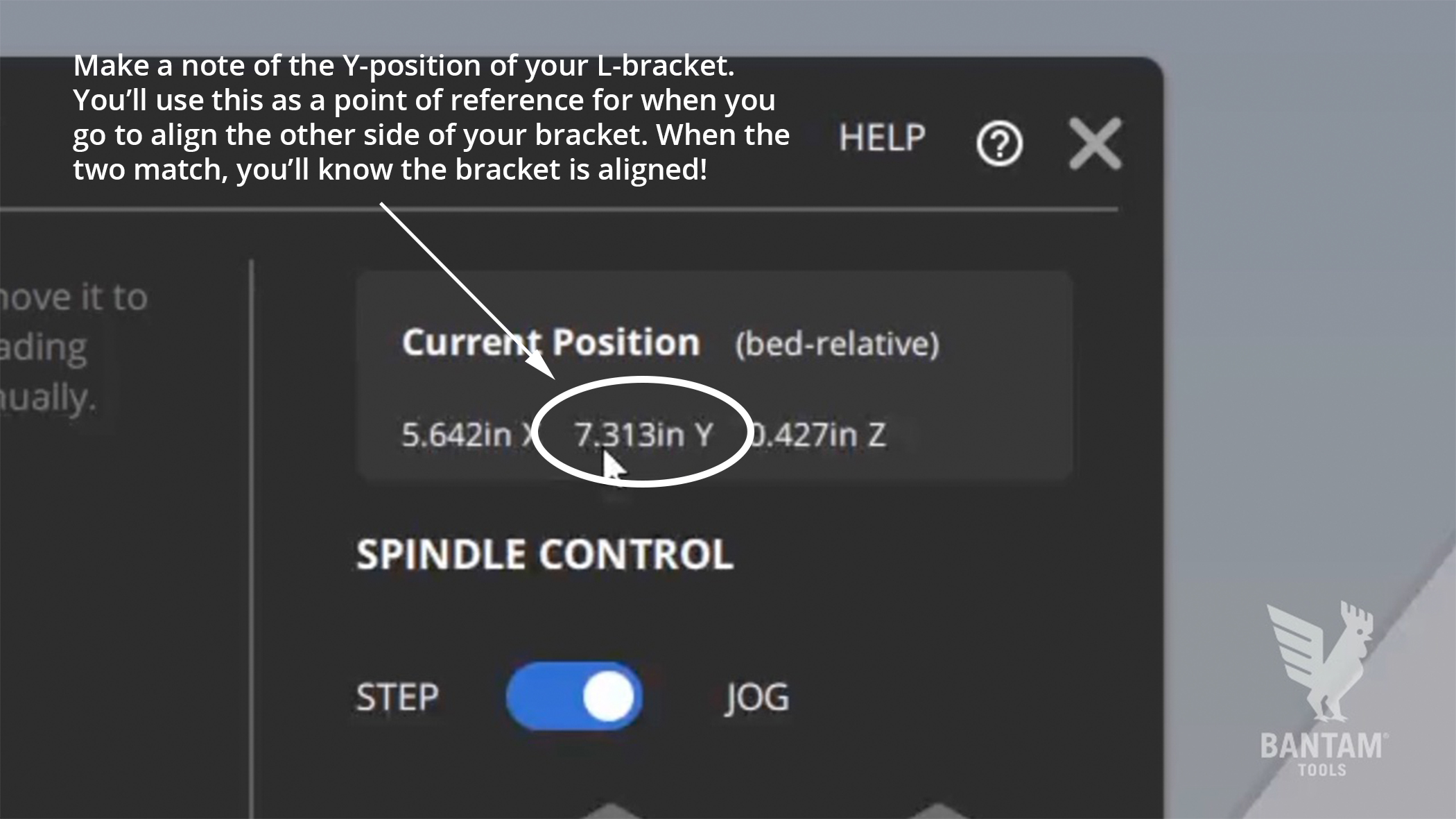
Next, jog the probe away from the bracket and move it into position by the screw that’s on the far end of the L-bracket. Use the same Probe Y command until the probe touches the L-bracket. Again, when it stops, note the Y-position.
If the numbers don’t match, move the probe out of the way and slightly move the bracket forward or back. The direction it needs to move is dependent on the readings you got. If you’re probing from the front, the Y value will increase (+) when you adjust the bracket toward the back of the mill and decrease (-) if you adjust it forward.
Be patient, this may take a few adjustments and rounds of probing. After you’ve made an adjustment, re-probe the bracket then repeat the process until you get the Y reading at both screws to be equal.