Difficulty Level
In this project, you’ll machine a pocket-sized machinist rule using the advanced SVG workflows in the Bantam Tools Desktop Milling Machine Software. What's the difference between a "rule" and a "ruler"? Generally, a rule measures straight from its edge (while a ruler's measurements start a little in from the edge) and is more accurately calibrated. And what better way to make a precise tool, than by using a precise CNC machine!
Through building this project, you’ll learn how to:
- Work with color-coded SVG files in the Bantam Tools software.
- Align your material and plan with alternate probing techniques.
- Use high-strength, double-side Nitto tape to fixture your material to the T-slot bed.
- Perform a flip operation.
Tools
- Bantam Tools Desktop CNC Milling Machine
- Computer with Bantam Tools Desktop Milling Machine Software installed
- Datron single-flute flat end mill, 4 mm
- Metal engraving bit, 80º, 1/8”
- High-strength, double-sided Nitto tape
- ER-11 1/4" collet that comes with your machine
- ER-11 1/8” collet
- Scraper
- Isopropyl alcohol, 91%
Materials
- Aluminum stock, 4” x 4”x 0.125”
Files
If you're using the advanced SVG support in the Bantam Tools Milling Machine Software, these are the files you'll need to use:
- Machinist-Rule.svg file downloaded
- Machinist-Rule-Inscription.svg file (optional)
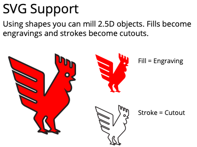
SVG (scaled vector graphic) files are 2D drawings that the Bantam Tools software can interpret and generate toolpaths. Any object in an SVG file with a border or fill will be machined. The Bantam Tools software looks at strokes and fills to determine the inside and outside of shapes in a design. The software combines the resulting shape with the tools you’ve selected, as well as the scaling, placement, and any other settings you specify. Then it calculates the toolpaths that the Desktop CNC Milling Machine will follow.
The Bantam software can interpret SVG files in two ways. Classic SVG handling reads fills as engravings and strokes as cutouts.
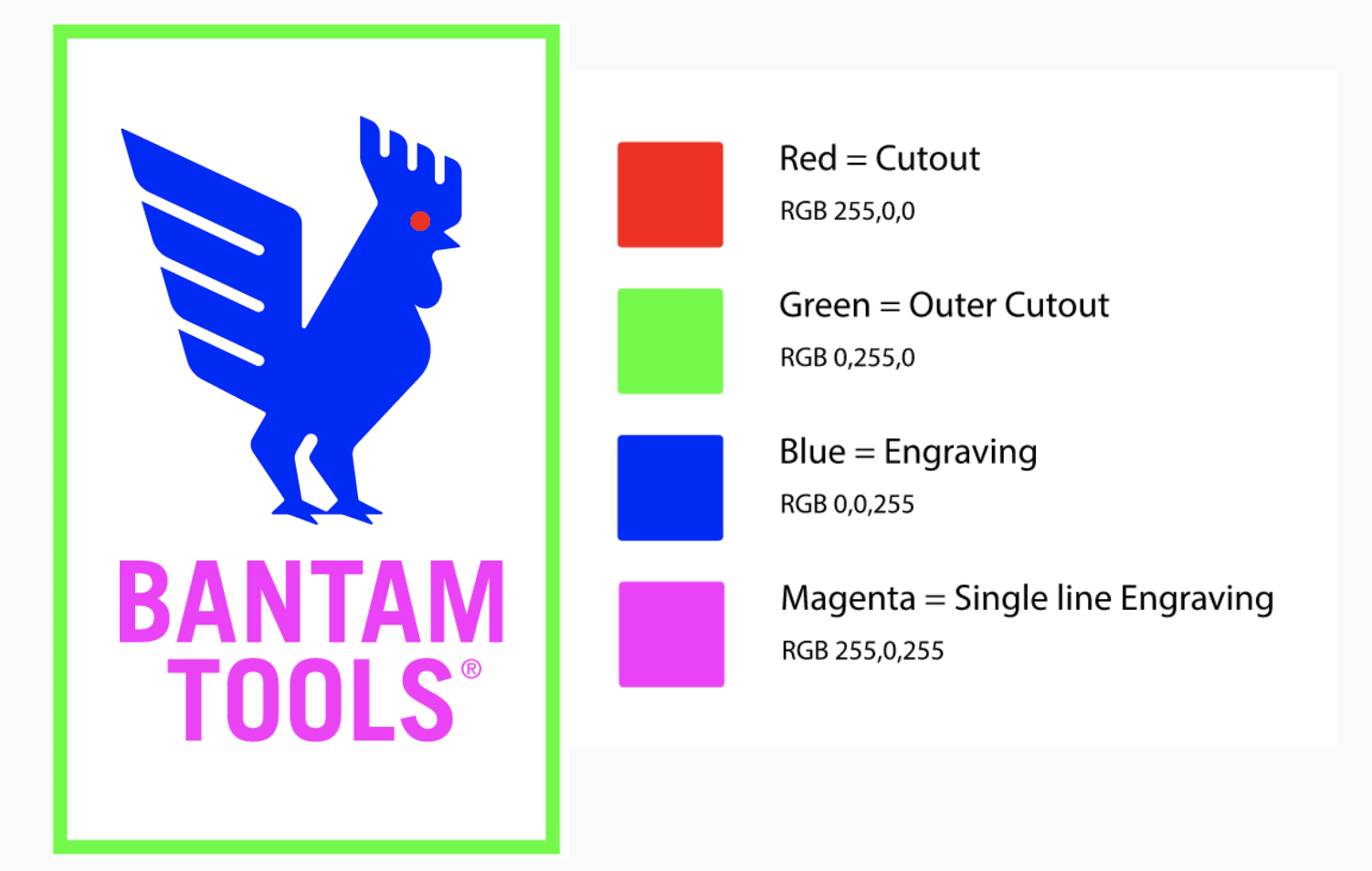
Advanced SVG handling allows you to do multiple cutout operations in one file using color coding. This project uses advanced SVG handling. Color layering lets you set colors in your SVG to assign multiple operations in a single file.
Note: If you're using Illustrator, you'll need to use a RBG color mode.
To learn more about working with SVGs, check out these resources:
- Download the Illustrator SVG Quick Guide template
- Download the Inkscape SVG Quick Guide template
- Read our Classic & Advanced SVG Workflows support guide.
A Note Before You Start Milling
The SVG project file we provide we designed specifically for the tooling and materials listed above. If you don’t have these end mills or stock, you will need to choose different tooling and may need to adjust the speeds and feeds parameters in the Tool Library before continuing to set up your job in the Bantam Tools Milling Machine Software.
Step 1: Import and set up your SVG file in the Bantam Tools software.
With all this in mind, let’s dive in!
Connect your Desktop CNC Milling Machine to your computer, turn on the machine, and launch the Bantam Tools software. Home the machine and then navigate to the Initial Setup tab and import the Machinist-Rule.svg file (link above). The file dropdown menu will look like this:
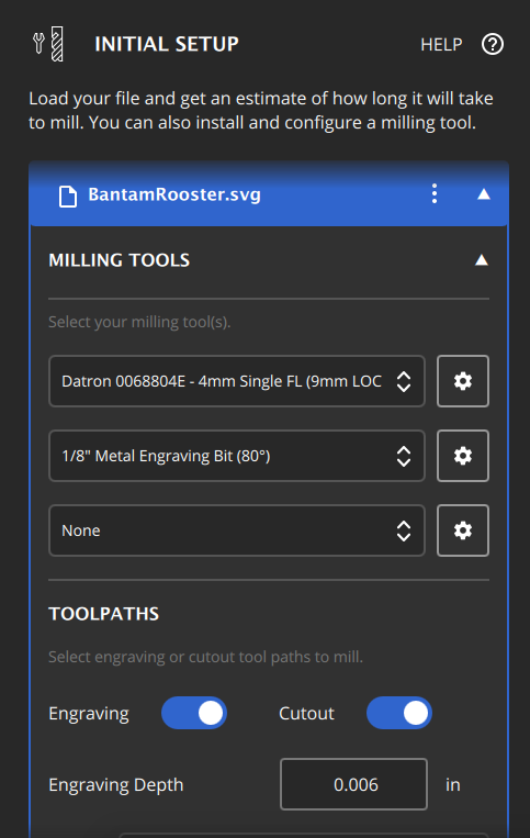
To set up your file:
- In the Milling Tools dropdown menu, select the “Datron 4mm Single-FL” and the “1/8” Metal Engraving Bit (80º)”. If you click the gear icon next to each tool you’ve selected, you’ll open the Custom Tool Library, where you can copy a tool and customize the speeds and feeds. We’ll be using the default speeds and feeds in the tool library for these two tools.
- Then, under Toolpaths, change your Engraving Depth to 0.003”.
- Scroll down to the Advanced SVG dropdown menu. Select “Use Advanced SVG Handling”. This tells the Bantam Tools software to interpret the colors in our SVG as different milling operations.
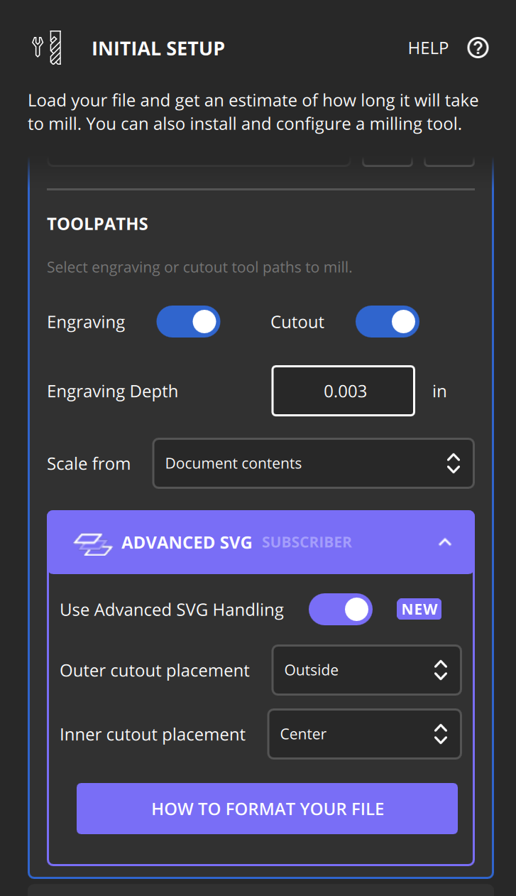
Note: If you're using the classic SVG support, you'll need to import in both the Machinist-Rule.svg and Machinist-Rule-Inner-Cutout.svg files. For the Machinist-Rule.svg select the Datron 4 mm single-flute and 1/8" Metal Engraving Bit (80º) end mills and then for the Machinist-Rule-Inner-Cutout.svg select the Datron 4 mm single-flute end mill.
Step 2: Install your ER-11 1/8” collet.
The collet that comes with your Desktop CNC Milling Machine supports 1/4” tooling. However, if you’re going to use smaller tooling––like we are in this project––you’ll need to use a collet that supports smaller tooling. To ensure accuracy and compatibility, we recommend using the ER-11 collet in our store.
To install the collet:
- Remove the collet nut from the bottom of the tool holder. Use the smaller wrench on the flat part of the tool holder to secure it in place, and then use the larger wrench to unscrew the nut.
- Remove the 1/4” collet from the collet nut.
- Insert the 1/8” collet into the collet nut—you’ll hear it snap into place.
- Screw the collet and collet nut back onto the tool holder with two or three turns, or use the wrenches, if necessary. Remember, don’t fully tighten the nut without a tool inserted.
Step 3: Install and locate the 1/8” engraving bit.
Have the 1/8" ER-11 collet installed? Great! Head down to the Jog tab in the Bantam Tools software and select the Install Tool button. Select the 1/8" Metal Engraving Bit (80º) in the dropdown menu. Because 1/8” bits tend to be shorter than 1/4” bits, you’ll need to insert the tool less than 3/4” into the collet. See our Installing & Locating a Tool support guide for more details.
Then, follow the on-screen prompts in the pop-up window to run the tool touch-off routine.
Step 4: Prep and load your stock.
Once your tool is loaded, it’s time to prep and load your stock into the Desktop CNC Milling Machine. Navigate to the Material Setup tab. Using digital calipers, measure the dimensions of your stock and enter them into the X, Y, and Z values in the Material Size dropdown menu. When you’re finished, click Next.
You’ll then be brought to the Material Placement dropdown menu, where you will need to account for the Z-height offset of your material due to the double-sided Nitto tape. This is important because if you do not account for the thickness of the tape you run the risk of machining into the T-slot bed.
Enter 0.006” as our Z-offset value. This is the value we always use when working with double-sided Nitto tape we carry in our store.
You can click Next again since we’ll be using high-strength, double-sided Nitto tape to fixture this stock. We won’t use the toe clamps for this job, so you can remove them from the machine if they’re installed. We’ll be using the L-bracket to act as a backstop for our material.
Double-sided tape is a great fixturing option for when you’re machining thin pieces of stock. And don’t worry, it’s so strong that you may need 91% isopropyl alcohol to remove your part from the T-slot bed.
To prep your stock:
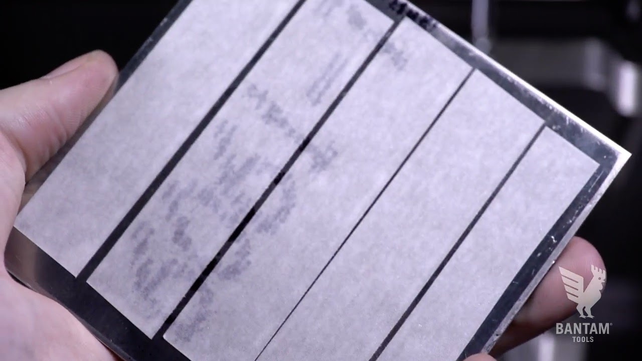
- Ensure the surface of your aluminum stock is clean, and cover as much surface area as you can with double-sided tape. Make sure the strips don’t overlap or wrinkle because this will affect your Z thickness.
- Remove the paper backing from the Nitto tape after applying.
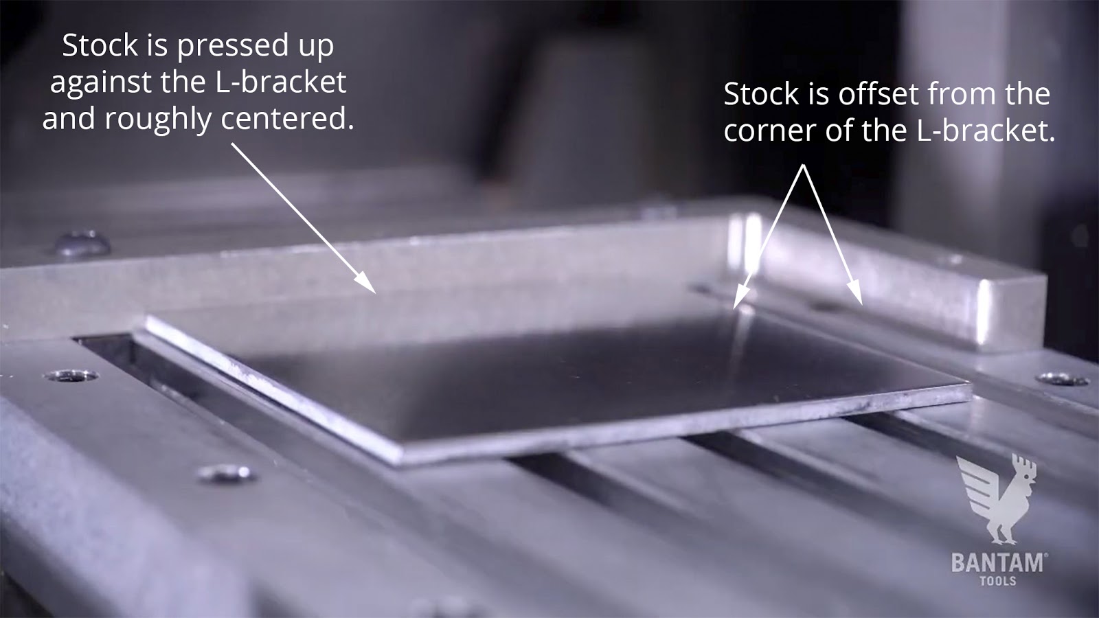
- Now press the material into place on the T-slot bed using the L-bracket as a backstop, and center it on the bed.
Step 5: Locate your stock.
Because we’re working with such a thin piece of stock, we’ll use the Manual Stock Location routine to configure the X and Y offset for our material, as opposed to the Automatic Stock Probing routine. The thinnest piece you'll be able to probe using our automated probing routines is 0.118" (3 mm). The reason for this limitation is because this would require jogging the probe into position very close to the machine bed and we want to help users avoid collisions.
Follow these steps:
1. Go to the Material Setup tab, click the Material Plan Offsets Probing Routine button, and select the Manual Stock Location Probing routine. A pop-up window will appear that looks like this. For both the X Zero and Y Zero select "Center."
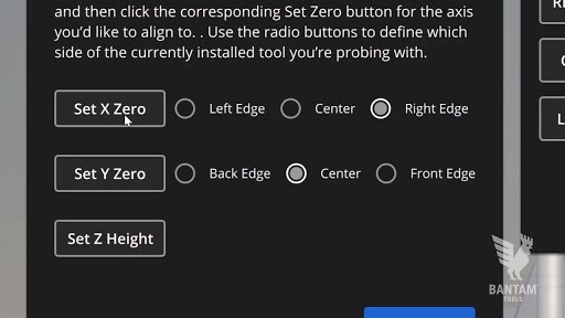
4. Okay, let's set the X zero. Using the jog controls, move the 80º metal engraving bit so that the center (or tip) of the end mill is hovering over the left edge of the stock. It's okay if you're a little bit off because we'll be jogging our plan toward the middle of the material in the next step. When you've jogged the tool into place, click Set X Zero. Important: To avoid breaking the tip, do not touch the tool to the material.
5. Now let's set the Y zero. Using the jog controls, move the 80º metal engraving bit so that the center of the end mill is hovering over the front edge of the stock. Again, it's okay if you're a little bit off. When you've jogged the tool into place, click Set Y Zero. Important: To avoid breaking the tip, do not touch the tool to the material.
6. When you're finished, click Next and then Accept.
Note: To learn more about the Manual Stock Location routine and other material and plan placement probing routines, check out our Material & Plan Placement Probing Routines support guide.
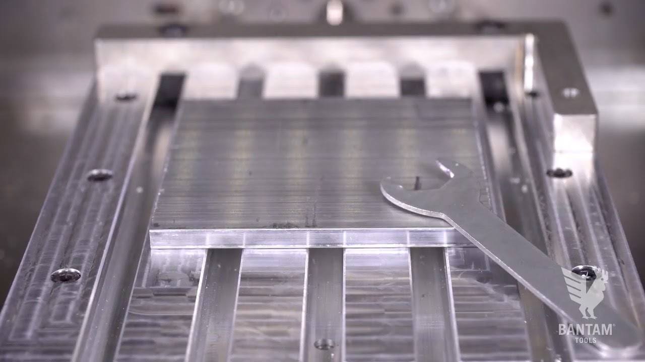
Before we move to the next, you'll need to determine the thickness of your stock. For this we will use an automated probing routine. To bridge the conductive loop between the stock and the machine bed, lay the collet wrench down so that one part is on the stock and the other is on the machine bed.
Now you're ready to us the Z-only Stock Probing routine. In the Material Setup tab, select the Material Offset Probing Routines and click Z-only Height Stock Probing. A pop-up window will appear. Follow the onscreen instructions to probe the thickness of the material. After running the probing routine, click Accept.
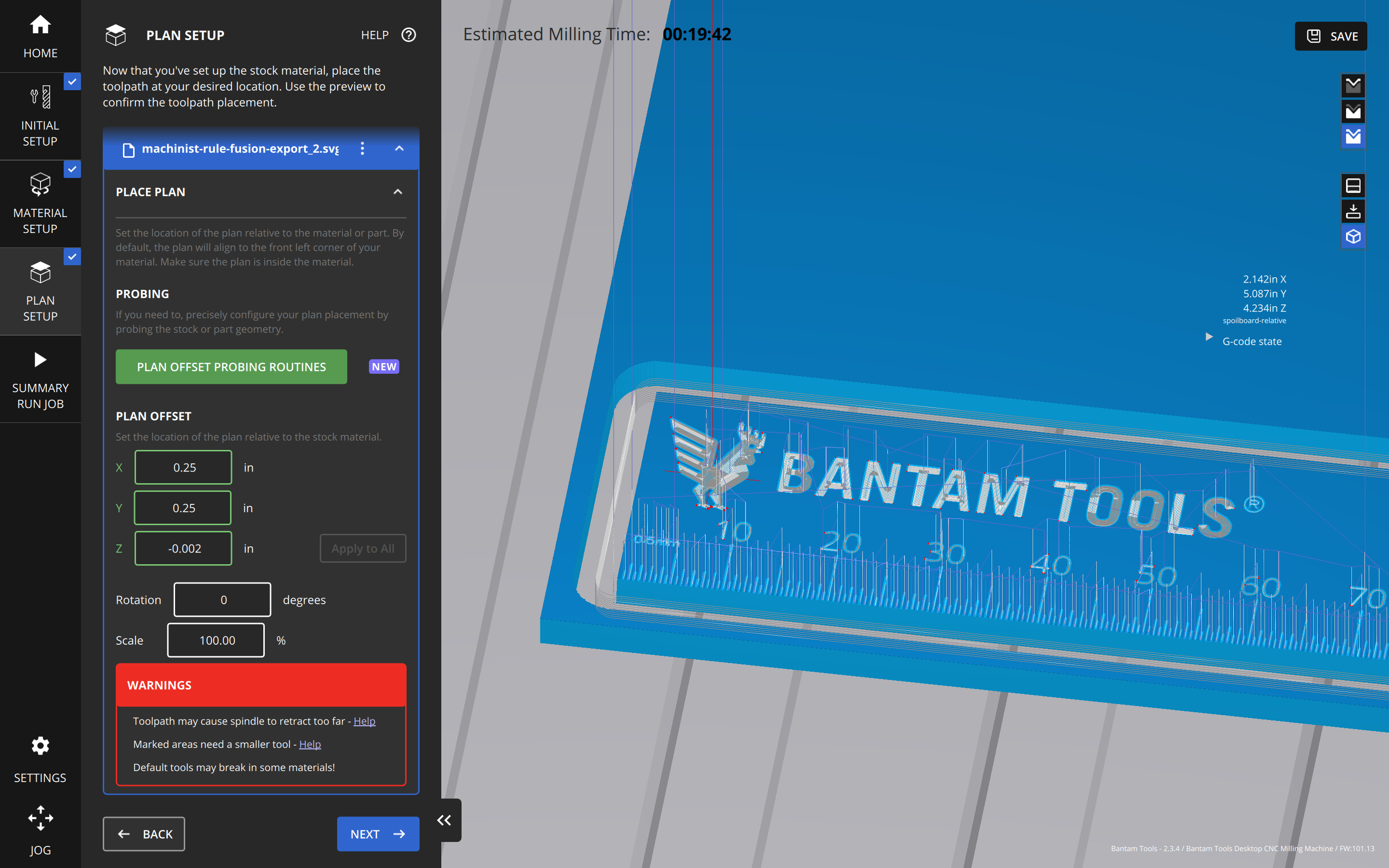
Step 6: Configure plan placement.
Head to the Plan Setup tab. Before you probe your plan placement, take a moment to look at the Scale value in the Plan Offset dropdown menu. When you load an SVG into the Bantam Tools software, it will automatically scale down if the stock’s dimensions you previously had entered were too small to fit the whole design. Now that you’ve updated your stock’s dimensions, the SVG will not automatically scale back up to 100%. You can correct this by adjusting the Scale value to 100%.
Now that you’ve located your material, it’s time to configure your plan Z height and enter your plan X and Y placement. Plan placement routines allow you to align your plan to a point other than the default location of the top left corner of your stock.
Click the Plan Offset Probing Routines button, and select Conductive Stock Probing to launch the Single-Axis Probing routine.
- Jog the spindle over the workpiece.
- Because the material isn’t in direct contact with the bed, you’ll need to create a conductive loop. Using one of the collet wrenches, place one end on the stock and the other on the T-slot bed.
- When you’ve closed the loop, click the Probe Z- button.
- When the probe comes in contact with the stock, it will stop. Click the Set Z Zero button. Then use the jog controls to back off of the workpiece.
- Click OK.
The Z value under Plan Offset has now been updated.
Before you start milling, we’ll use the manual plan position controls to adjust your plan placement within the stock. Adjust the X and Y values under Manual Placement as well, so that the plan is 1/4” (0.25) away from the material edge. This will give you extra material as a buffer between the design and the edge of the stock.
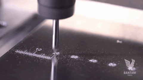
Step 7: Start milling!
Go down to the Summary tab to review your job. When you’re satisfied, click the Mill Single File button and watch your Desktop CNC Milling Machine go to work!
When the machine is finished engraving, it’ll pause and you’ll be prompted to swap the 80º metal engraving bit for the 4 mm single-flute end mill.
Remove the metal engraving bit and collet, insert a 1/4” or 6 mm collet into the collet nut, then insert the 4 mm single-flute end mill, and perform a tool touch-off. The mill will proceed to machine the internal and outer cutout.
Step 8: Remove your part from the Desktop CNC Milling Machine.
Use a scraper to remove your machinist rule from the T-slot bed. We also recommend using 91% isopropyl alcohol to break down the adhesive in the double-sided tape, which makes it easier to remove the part. Apply a little bit of 91% isopropyl alcohol around the edges of your stock and within the cutout of your part. Let itsit for a minute or so and then carefully use the scraper to take the part off the bed.
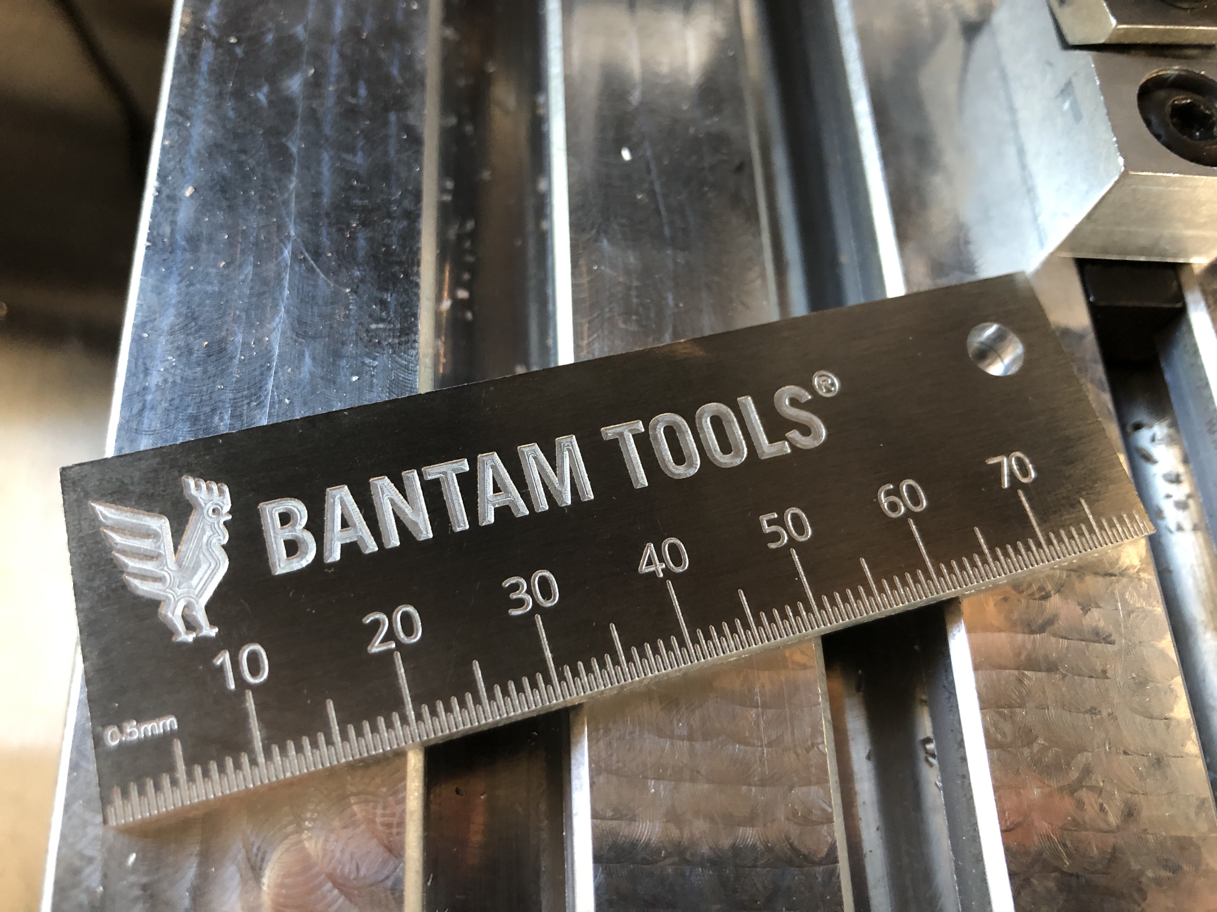
Congrats! You now have a handy machinist rule that you can easily carry around with you. If you want to stop here, go measure some stuff! But there’s one more thing you can do: customize the back.
Advanced: Perform a Flip & Customize Your Machinist Rule
Step 9: Measure, flip, and fixture your part.
Glad to see you’re game for adding a custom design to your machinist rule! Let’s start by performing a simple flip. Using the instructions outlined in Step 4, prep the other side of your machinist rule (the front side that you just machined) by applying double-sided tape.
Step 10: Create a custom engraving.
If you’d like to add the “Measure twice, cut once” inscription on the back of your machinist rule like we did, then download the Machinist-Rule-Inscription.svg file and skip to Step 11 to set up your SVG file. However, if you’d like to create your own SVG design, read on!
There are a number of ways to create designs for your SVGs:
- Create them from scratch in a design program. Some of our favorite programs are Inkscape and Adobe Illustrator. Open the program of your choice and create your SVG. When you’re finished, save your SVG.
- Save an image or clip art (simple, black and white images work best) and format it as a vector graphic.
- Draw your own design or take a picture, and save it as an SVG.
If you’d like to learn more about creating SVGs in Inkscape or Illustrator, check out these helpful templates and support guide.
- Download the Illustrator SVG Quick Guide template
- Download the Inkscape SVG Quick Guide template
- Read our Classic & Advanced SVG Workflows support guide.
For this project, we used Inkscape because it’s free and its default is to save files as SVGs—exactly what we need!
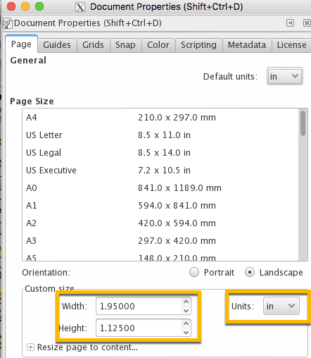
Download Inkscape and open the program. It will automatically create a new document. Before you start designing, set your canvas dimensions to match the size of your machinist rule.
Click File > Document Properties, and in the Custom Size window, change the units to inches (in).
Measure the height and width of your machinist ruler, enter these dimensions under Custom Size, and save your file.
Create a design of your choosing using any of the three methods mentioned above, and format your design as a vector graphic. If you need more information on how to do this, see our Classic & Advanced SVG Workflows support guide.
Classic SVG handling will suffice for this custom design, so you won’t need to worry about color-coding your design.
When you’re done, click Save and head over to the Bantam Tools software.
Step 11: Set up your custom engraving file.
Go to the Initial Setup tab in the Bantam Tools software and remove the Machinist-Rule.svg file, if you haven’t already. Then import the SVG design file you just created. Again, we’ll only be using the classic SVG workflow for this operation. Complete the following steps to set up your SVG file:
- In the Milling Tools dropdown menu, select the tool(s) your plan calls for.
- In the Toolpaths dropdown menu, deselect Cutout.
- Change your Engraving Depth to 0.003”––or to the depth of your choosing.
When you’ve finished setting up your file, make sure there are no (or minor) red warnings on your SVG design. If the majority of your SVG is highlighted with red warning marks, you’ll want to select a smaller tool—in some cases you may even need to go back and tweak your design.. When you select your new tool the realtime preview in the Bantam Tools software will update. If most of the warnings have been resolved, continue to the next step!
Step 12: Probe stock location and Z height.
Install your end mill you and then head to the Material Setup tab. Click the Material Offset Probing Routines button, select Manual Stock Location routine, and follow the instructions outlined in Step 5. Once you’ve located your stock, go to the Plan Setup Tab and click the Plan Offset Probing Routines button and select Conductive Stock Probing to launch the Single-Axis Probing routine. Use the same method outlined in Step 6 to probe the Z height of your stock.
Step 13: Install your end mill, review your job summary, and start milling.
Click the Jog tab and select Install Tool. After you’ve performed the tool touch-off, go to the Summary tab and review your job. Be sure that there are no red marks or warning signs. When you’re satisfied, click Mill Single File.
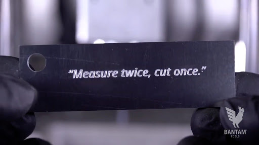
Boom! You’ve just created your very own custom engraving for your machinist rule. Remove your part from the machine and start measuring. Remember: Measure twice, cut once!